JAPton blog

Discussions and updates on your new bike, your new build, your wishes, wants and desires
User avatar
Rockburner
Posts: 6010
Joined: Sun Mar 15, 2020 11:06 am
Location: Hiding in your blind spot
Has thanked: 10930 times
Been thanked: 3975 times

Re: Re: New Project(s)

Post by Rockburner »

Hmmm - looking at this....

Image
Those suspension mounting brackets are not standard...

The wideline frame doesn't have cupped shock mounts either :
Image


Anyone got a lathe?
non quod, sed quomodo
User avatar
Rockburner
Posts: 6010
Joined: Sun Mar 15, 2020 11:06 am
Location: Hiding in your blind spot
Has thanked: 10930 times
Been thanked: 3975 times

Re: JAPton blog

Post by Rockburner »

Did some more tinkering on Friday night:

This is the dural bar I mentionted previously:
Image

The intention is to use these two holes - yes, yes one of the bolts is the upper shock mount, but it'll be fine.... ;)
Image

Just a shot of the general arrangement of what's under the saddle unit:
Image

Current shock mounting bolt on bottom... hmmmm
Two found 3/8" bolts above - much better shanks!
Image

"Found" bolts is pretty much the right length (2"), but not completely convinced that the shank is long enough.
Image

Ideally the shank of the bolt should interface with the inner part of the shock mounting plates as well as the full width of the shock eyelet. This is to reduce shear forces on the bolt - thread forms are a weak point when dealing with shear forces.

The Allen-head bolts looks trick.... so if I end up searching for custom bolts I "may" go back to Allen heads - but the hex-head is a loer profile which bh, I think I prefer.
Image


I was cleaning up the botls and looking for possible bits and pieces to convert into spacers, but I had a bit of a blocker happen when I used one of the new Cycle thread Dies to clean up the thread on one of the bolts. They were a bit manky (but good), so I cleaned them in the usual style with a bras brush, but then decided to spin the Die down them as well. Loaded the die in the stock for the first one, and started running it down the thread.

Hm - this is a bit stiffer than I expected... but maybe the gunk in the bottom of the threads is harder than I though.... carry on...

Got most of the way down the thread and took a much closer look - and realised in shock that the thread had been destroyed! The top half of the thread form had been scraped off uniformly all the way down! I ran a cycle nut down the thread and it IS a cycle thread, checked the other found bolt against the TPI guage, yup - 26TPI, and the mutated thread on the bolt also checked out as 26tpi. Checked other known 26tpi bolts and nuts....


the friggin Die is damaged, or badly made. :angry-cussingblack: :angry-cussingblack: :angry-cussingblack: :angry-cussingblack:

Checked the other dies from the same purchase, and where I had a known good bolt - the dies ran fine (1/4" and 5/16" seems to be all I have in known good bits and bobs).

So - going to have to ring the supplier today and see what can be done. Thankfully I've only wrecked one bolt... but it's a tad frustrating. :roll:


I've also been thinking about these bolts and where to get bolts with a proper long shank, and I think I'm probably just going to have to get the longest 3/8" bolts I can find, with the longest shanks and turn down the thread to match what I need. Buying custom made bolts will most likely be ruinously expensive, I don't really need 1000+ of the bloody things. :D
non quod, sed quomodo
JackyJoll
Posts: 4439
Joined: Sun May 03, 2020 10:11 pm
Has thanked: 245 times
Been thanked: 1227 times
Contact:

Re: Re: New Project(s)

Post by JackyJoll »

Buckaroo wrote: Mon Nov 03, 2025 12:19 pm I hope this isn't a daft question, but do they need to weigh the same amount?
I’ve had a think and I don’t think there’s any reason the inlet rocker should weigh the same as the exhaust one, except that it’s a vaguely “good thing” for them both to be light and rigid.
JackyJoll
Posts: 4439
Joined: Sun May 03, 2020 10:11 pm
Has thanked: 245 times
Been thanked: 1227 times
Contact:

Re: Re: New Project(s)

Post by JackyJoll »

Rockburner wrote: Fri Nov 21, 2025 10:01 am]
Image

The shock uppers have at least 1/2" of movement side-to-side!! :wtf:
I kind of had the opposite thing on my Wideline when I bought cheapo EMGO shocks, ordered by size not application: the brackets on the frame were too narrow for the eye of the shock.

Fixed with a file.
Supermofo
Posts: 5951
Joined: Mon Mar 16, 2020 3:39 pm
Has thanked: 5936 times
Been thanked: 3551 times

Re: JAPton blog

Post by Supermofo »

Must say I love reading about your tinkerings with the JAPton, well written, entertaining and enlightening. I have no clue as to half of what you're doing but it's a bloody good read none the less and fully explained with pics. Top work.
User avatar
Rockburner
Posts: 6010
Joined: Sun Mar 15, 2020 11:06 am
Location: Hiding in your blind spot
Has thanked: 10930 times
Been thanked: 3975 times

Re: JAPton blog

Post by Rockburner »

Supermofo wrote: Tue Nov 25, 2025 9:52 am Must say I love reading about your tinkerings with the JAPton, well written, entertaining and enlightening. I have no clue as to half of what you're doing but it's a bloody good read none the less and fully explained with pics. Top work.
Very kind of you to say! Thank you.

A lot of this is a reaction of sorts to the fact that my Dad left no notes whatsoever, so i think I'm possibly overdoing it in places, but with luck I'll be able to use this thread as a historical reference in the future. It's also quite fun to write all this rubbish. :D
non quod, sed quomodo
User avatar
Rockburner
Posts: 6010
Joined: Sun Mar 15, 2020 11:06 am
Location: Hiding in your blind spot
Has thanked: 10930 times
Been thanked: 3975 times

Re: JAPton blog

Post by Rockburner »

I've had another project on the workbench for the past week, but managed to find myself at a loose end on Saturday morning.... always dangerous...

I found myself looking at the wiring "loom" on the JAPton and thinking how messy it looked....
Especially things like this connector block near the battery :
Image

The connector block cable-tied to the cross-beam visible in this photo: (left of photo, lower part of cross-beam)
Image

And especially this mess:
Image
In regards to this - I really dislike the way the horn (black button) wire just dangles down to the headstock.

So - I perused, and pondered, and tinkered and eventually...

Image

Yes the horn IS wired in.

Image
Image
Image
Image


No new holes were drilled - all these holes were pre-existing (for one reason or other...)


A make-do 'grommet' at each end
Image
Image


At the other end - the feed wire to the brake light has always bothered me because it was pulled quite taut, so I soldered on an extension to the yellow wire (which is the wire between the brake light switch and the bulb), and gathered up the few wires that actually needed to be all together with a Wago instead of a shitty plastic screw block. The Wago is glued to the battery.
Image
Image


Much neater.
Image

The entire wiring circuit is simple 2 loops - one for the brake light:
Battery -- switch --- bulb --- battery.

And one for the horn:
Battery --- horn --- switch --- battery.

It's currently setup as a "positive earth" with the frame as earth - so both the horn and brake-light simply earth to their nearest bit of metal, and the battery has a wire from the + terminal to the frame. Nice and simple.

The 3rd "out" connection at the Wago is for a battery charger connection that I wired in so I could charge the battery directly without removing the seat.

I may try to do a bit more tidying up - the horn wires are just loose and could probably do with "looming" together at some point, and similarly the group at the Wago could be tidied, but generally I'm happy with the end result.

There is also the Kill-switch to be replaced - but that will be moving to the right handlebar and is part of the Mag/coil/plug wiring circuitry which are totally separate from the "ancilleries" wiring. Yes - there's no way to charge the battery, so it has to be charged up before a ride... but it's "only" powering the horn and brake light (the brake light will be replaced with an LED at some point) so it's just a case of making sure it's charged before use.

Nasty looking little home-made implement for hooking wires through holes.... may well come in handy. (made from a dentist pick that had lost it's end.)
Image
Image
non quod, sed quomodo
User avatar
Rockburner
Posts: 6010
Joined: Sun Mar 15, 2020 11:06 am
Location: Hiding in your blind spot
Has thanked: 10930 times
Been thanked: 3975 times

Re: JAPton blog

Post by Rockburner »

Remembered I had some loom tape yesterday, so completed the job:

Image

Image

I also took some remediating action concerning the battery flopping about on it's single screw....
Image

Will help for now - but a better solution will be engineered eventually.
non quod, sed quomodo
User avatar
Rockburner
Posts: 6010
Joined: Sun Mar 15, 2020 11:06 am
Location: Hiding in your blind spot
Has thanked: 10930 times
Been thanked: 3975 times

Re: JAPton blog

Post by Rockburner »

Managed a couple of hours yesterday in the workshop:

Polished up what I could get to on the conrod :
Image

And the sides of the fly-wheels:
Image

Probably won't make a gnat's chuff of a difference but it felt like the right thing to do. Someone's had a go at the flywheels with an angle-grinder by the looks of it, so a mirror finish ain't gonna happen, but they're a lot shinier now

Then turned my attention back to the mag-platform bracket. I want to get this sorted before I assemble the crank in the cases because dealing with the cases and how they fit in the bike is a lot, lot easier when they're empty!

I spent about an hour repeatedly heating and belting the hell out of the bracket I'd previously made to try to get it to reach the smaller case-bolt where it's "supposed" to mount to.
Image

This is as close as I could get it:
Image

To be honest, I think that bit of steel has had enough of me hammering at it.

So, I dug out another couple of potential victims:
Image

Will assess these for suitability and have another go next time.
non quod, sed quomodo
JackyJoll
Posts: 4439
Joined: Sun May 03, 2020 10:11 pm
Has thanked: 245 times
Been thanked: 1227 times
Contact:

Re: JAPton blog

Post by JackyJoll »

The holes in the frame for the horn wire will let rain water into the frame tubing.

Frame earth return is good enough for the horn and kill switch, so long as the forks have continuity to the main frame through a wire (not just through the steering head bearings.

Lights, ignition and charging system need return leads for reliability. Relying just on frame and casing connections causes breakdowns, eventually.

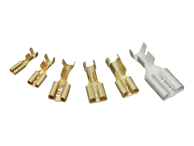
The red and blue plastic pre-insulated crimped connectors aren’t as good as Jap type with a W crimp and separate insulating sleeves.

Image
User avatar
Rockburner
Posts: 6010
Joined: Sun Mar 15, 2020 11:06 am
Location: Hiding in your blind spot
Has thanked: 10930 times
Been thanked: 3975 times

Re: JAPton blog

Post by Rockburner »

JackyJoll wrote: Fri Dec 05, 2025 10:16 am The holes in the frame for the horn wire will let rain water into the frame tubing.

Frame earth return is good enough for the horn and kill switch, so long as the forks have continuity to the main frame through a wire (not just through the steering head bearings.

Lights, ignition and charging system need return leads for reliability. Relying just on frame and casing connections causes breakdowns, eventually.

The red and blue plastic pre-insulated crimped connectors aren’t as good as Jap type with a W crimp and separate insulating sleeves.

Image
All true, but in mitigation:

It's a sunny days only bike, and those holes in the frame were already there (there's more too), as said - I didn't make any new ones - just used the ones that were already there.

My Dad's bikes have used those cheap handlebar switches and never had an issue, and if the horn was in any way a "must have" item I would consider an earthing "strap" (trust me, you can't hear the horn over the exhaust!)

There are no lights, ignition or charging systems in this loom. :D (apart from the single brake light, which might... might get a return wire if I start getting issues with it.)

Yeah - the crimped connectors aren't perfect, but they're what I had and eventually might get replaced (I think there's enough slack in the wires to redo them if needed.)
non quod, sed quomodo
User avatar
Rockburner
Posts: 6010
Joined: Sun Mar 15, 2020 11:06 am
Location: Hiding in your blind spot
Has thanked: 10930 times
Been thanked: 3975 times

Re: JAPton blog

Post by Rockburner »

Mag-Platform bracket mk2:

In progress:
Image

In place:
Image


To be honest.... I'm not convinced. I bent that bit of steel cold, with just a hammer and then twisted it with mole grips. I think it's just a bit of mild and may not provide the support that I would get with the thicker stuff. :(

But - it'll do initially and I can have another go if I decide I want to. At least now I have a "pattern" piece for reference when making another one.

I made this one by doing the bend first: after figuring out roughly where it should be with the bracket bolted to the cases; then I put the twist in to bring the upper hole (the mag-platform end) into alignment with the underside of the mag platform. However - that meant that the twisted part of the bracket works against getting the bracket flat against the mag-platform.

If I try again, I'll probably start at the other end - the mag-platform end, and work out what the bend needs to be from that end. I thinkt it could be done with a single bend, but at a funny angle across the bracket, it's not quite 45 degrees - maybe about 30 or so.
non quod, sed quomodo
User avatar
Druid
Posts: 1270
Joined: Mon Mar 16, 2020 7:45 pm
Has thanked: 351 times
Been thanked: 1106 times

Re: JAPton blog

Post by Druid »

That seems to be an excellent opportunity to employ some CAD*


*Cardboard aided design.
Shamelessly nicked from Project Binky
User avatar
Rockburner
Posts: 6010
Joined: Sun Mar 15, 2020 11:06 am
Location: Hiding in your blind spot
Has thanked: 10930 times
Been thanked: 3975 times

Re: JAPton blog

Post by Rockburner »

A few more steps in the journey on Friday night last:

I ordered up some bolts for the rear-shock mounts, but there was a communications failure and they turned up with the wrong specs:

The shank length should be 1"5/8s, (1.675"): hey ho... more on the way... I'm sure these will be useful somewhere else.
Image

I want the shank that length specifically so that the threads are not bearing on the inner mount plate, but the shank is.

New spacers for the rear-shock mounts: these are perfect (and a right git to fit).
Image

I inadvertently undid the nut & bolt I put into the valve-lifter pivot hole, so replaced it, and used a felt washer to attempt to make it a touch less prone to weeping.
Image

Thinking about it now... I may add a lock washer or a nyloc to that....

I also realised that I hadn't offered up the cases with the mag-platform bracket into the frame and engine plates. So after a bit of swearing and cajoling I put the empty cases back in the mounts (I'm really not looking forward to that job when the engine is fully assembled!)
The bracket clears the plates nicely.
Image

Image


I also took the opportunity to drill a little hole in the flange that protrudes from the output side engine case:
Image

The reason for that hole is that the engine oil drain bolt has a lockwire hole in it, and it was lockwired before (for good reason...), but Dad had the lockwire attached to a cut down penny washer that was under the bolt on one of the engine case screws. It just always seemed untidy, so - this way, the drain plug can be lockwired to the engine case itself and it's a neater job.

I've no idea what the flange is for - there are some numbers on there, but they're not the usual place for engine numbers, and I've not seen that flange on any of the engine diagrams or drawings I've seen - I think it "might" be an extra flange used on the stationary engines, eg ditch pumps, lawnmowers, generators etc (which are pretty much the same engine cases) to indicate... something!

I've also seen a few more engines in photos recently and they do often seem to have mag-platform brackets that aren't hugely chunky, so I'm going to go with the one I've made for now, and try to make some more progress.

Next job is make a few more paper gaskets for various covers and things that mount to the engine: the oil drain chest and vent chest covers both need one, and the cylinder base.

I was considering whether or not to try to "lap-in" the cylinder base to the engine cases, but I think I'll just go for a .4mm paper gasket. I've got some compression plates which should serve as templates for that gasket (they're normally used for reducing the compression so I won't be using them!).

Also need to heat-treat the copper cylinder head gasket, and I've got a few more spares too, so I may well just do them all at once, so the spares are ready to go. Trying to remember if they need to be quenched, or just left to cool down after I heat them to pink...
non quod, sed quomodo
iansoady
Posts: 504
Joined: Thu Mar 19, 2020 10:12 am
Has thanked: 72 times
Been thanked: 244 times

Re: JAPton blog

Post by iansoady »

Looking great. Re annealing copper - you can quench or not after getting cherry red. Doesn't make any difference but quenching helps to remove any scale the metal has.
User avatar
Skub
Posts: 14892
Joined: Mon Mar 16, 2020 5:32 pm
Location: Norn Iron
Has thanked: 13109 times
Been thanked: 14170 times

Re: JAPton blog

Post by Skub »

What Ian said. I've always done the cherry red/quench thing to soften copper. More or less the same process will case harden steel.
"Be kind to past versions of yourself that didn't know what you know now."
Walt Whitman
https://soundcloud.com/skub1955
iansoady
Posts: 504
Joined: Thu Mar 19, 2020 10:12 am
Has thanked: 72 times
Been thanked: 244 times

Re: JAPton blog

Post by iansoady »

I'm not sure if quenching steel will case harden as such. I usually quench steel in old engine oil in an attempt to harden it, often setting myself on fire in the process......
User avatar
Count Steer
Posts: 15869
Joined: Mon Jul 19, 2021 4:59 pm
Has thanked: 8005 times
Been thanked: 5664 times

Re: JAPton blog

Post by Count Steer »

iansoady wrote: Mon Dec 15, 2025 3:48 pm I'm not sure if quenching steel will case harden as such. I usually quench steel in old engine oil in an attempt to harden it, often setting myself on fire in the process......
From memory, simply quenching most steel will embrittle it but doing it in oil might just add a tad of carbon to the surface? High carbon steel will quench harden though.

Pure copper will definitely soften on quenching (it's what you do if you've work hardened it so you can get beating again). Some copper alloys like alloy bronze will quench harden.

(My final year Uni project was on the heat treatment of sintered tool steels but....it was a long, long time ago :D ).
The plural of 'anecdote' is not 'data'.
JackyJoll
Posts: 4439
Joined: Sun May 03, 2020 10:11 pm
Has thanked: 245 times
Been thanked: 1227 times
Contact:

Re: JAPton blog

Post by JackyJoll »

I stick the red hot copper gasket or washer in cold water right away.

Softens and descales it and saves me from burning my hand on it.
JackyJoll
Posts: 4439
Joined: Sun May 03, 2020 10:11 pm
Has thanked: 245 times
Been thanked: 1227 times
Contact:

Re: JAPton blog

Post by JackyJoll »

Your mag bracket things would be stiffer if the bends could be nearer the ends.
Post Reply